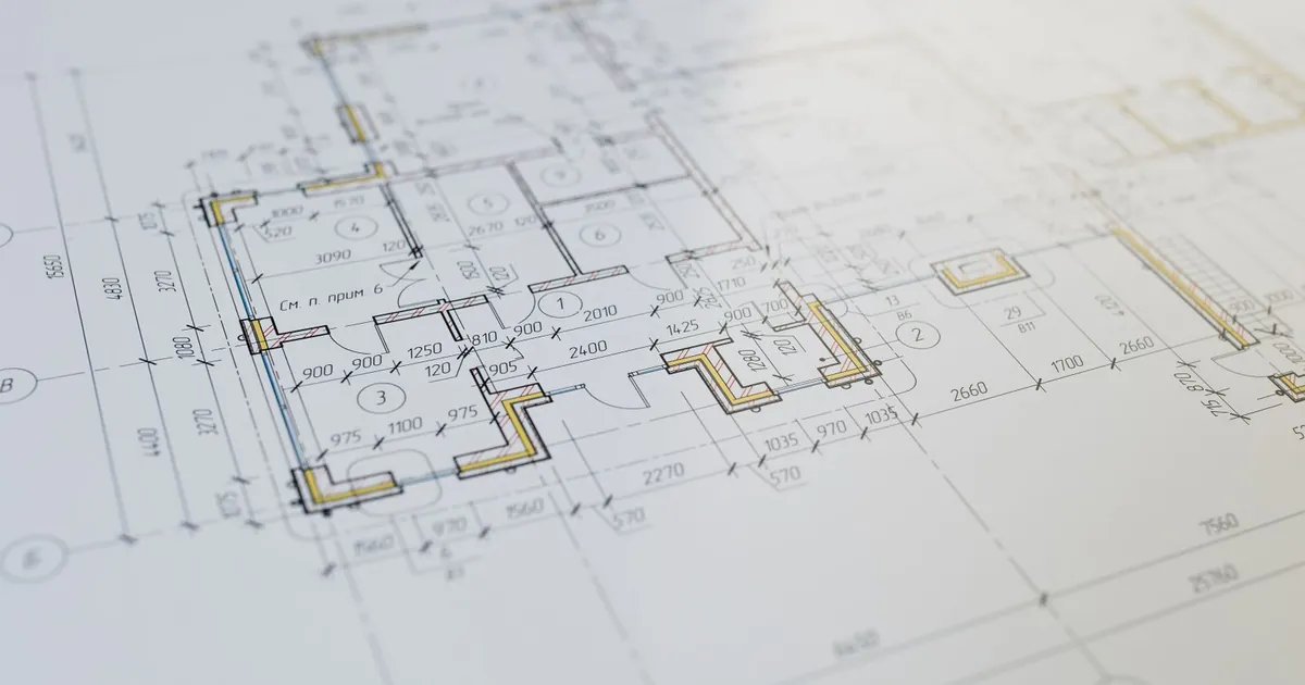
A pharmaceutical facility layout succeeds or fails on how people, materials, product and waste move through it. When those flows cross, no amount of HVAC capacity or gowning discipline fully repairs the problem, because the contamination route is built into the walls. This guide sets out what FDA and EU GMP Annex 1 expect from facility flows, how to route each one, and how to check a layout for crossings before it is frozen.
Key takeaways
- Facility layout is the arrangement of rooms, corridors and airlocks that decides how personnel, materials, product and waste move through a site, and GMP expects it to prevent contamination and mix-ups.
- 21 CFR 211.42(b) requires the flow of components, containers, closures, labeling, in-process materials and drug products through the building to be designed to prevent contamination.
- EU GMP Annex 1 (2022) expects personnel to enter cleanrooms through change rooms that act as airlocks, materials through separate airlocks, and transfers into grade A and B areas to be unidirectional.
- Waste, samples and rejected items should leave grade A and B areas by a separate unidirectional route; time-based separation by procedure is the fallback, not the first choice.
- Flow is a layout decision: a crossing is cheap to remove on a floor plan and expensive to remove once walls, doors and ductwork are built.
What is personnel and material flow in a pharmaceutical facility?
Personnel and material flow describes the routes that operators, components, equipment, product and waste take between the rooms of a pharmaceutical facility. It is the layout side of contamination control: each route is defined so that movement happens only in the way the design intends, and so that routes do not cross or share a space by accident.
Four flows matter in practice, and each one has its own routing rule.
| Flow | What moves | Routing rule | Source |
|---|---|---|---|
| Personnel | Operators, QC staff, maintenance | Enter through change rooms that act as personnel airlocks, moving through areas of increasing cleanliness (grade D to C to B) | Annex 1, 4.1 and 4.12 |
| Incoming materials and equipment | Components, containers, consumables, tools | Enter through material airlocks or pass-through hatches; transfer into grade A/B is unidirectional and limited to approved items | Annex 1, 4.11 and 4.12 |
| Product and in-process material | Bulk, intermediates, filled units | Flow through the building is designed to prevent contamination, with areas connected in the order of the process and the cleanliness levels | 21 CFR 211.42(b); EU GMP Chapter 3 |
| Waste and removals | Waste, environmental samples, rejected items | Leave grade A/B by a separate unidirectional process; time-based separation by procedure if that is not possible | Annex 1, 4.11 |
Annex 1 covers sterile products. For other dosage forms the general principles of 21 CFR 211.42 and EU GMP Chapter 3 apply, and the same routing logic is a sound starting point.
What do FDA and EU GMP require for facility flows?
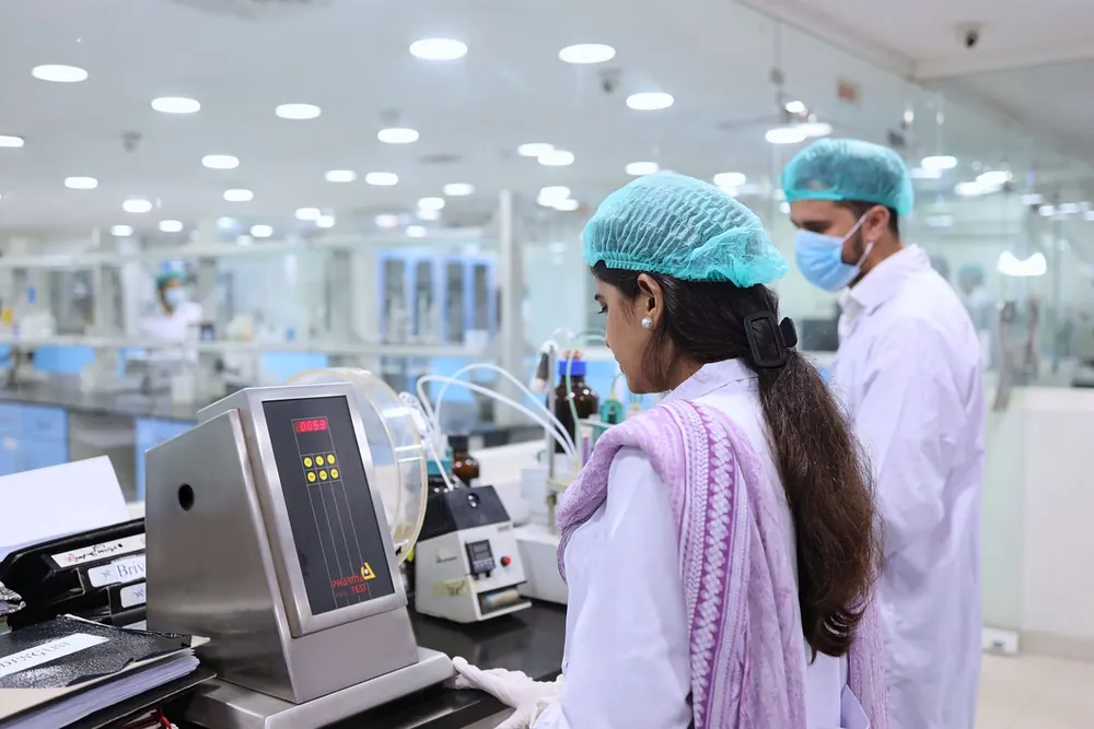
In the United States, 21 CFR 211.42 requires the flow of components, drug product containers, closures, labeling, in-process materials and drug products through the building to be designed to prevent contamination. It also requires separate or defined areas, or other control systems, for operations such as receipt and quarantine, storage, manufacturing, packaging, laboratory control and aseptic processing.
EU GMP Chapter 3 asks for premises laid out so that production takes place in areas connected in a logical order that follows the sequence of operations and the required cleanliness levels (see EudraLex Volume 4). For sterile products, EU GMP Annex 1 (2022) adds specific flow rules:
- 4.1: entry to cleanrooms through change rooms that act as airlocks for personnel, and airlocks for equipment and materials.
- 4.2: technical and operational separation between component preparation, product preparation and filling.
- 4.10: the transfer of equipment and materials into and out of cleanrooms is one of the greatest potential sources of contamination.
- 4.11: transfers into grade A and B areas are unidirectional, and materials, waste and environmental samples leave by a separate unidirectional process.
- 4.12 and 4.13: personnel and material airlocks are separated wherever possible, and doors of airlocks leading to grade A and B are interlocked.
How should you route personnel, materials and waste?
Give each flow its own defined route and its own airlock, and let routes meet only where an airlock and a pressure step separate them. Personnel step up through grade D, C and B change rooms, materials enter through material airlocks, and waste and removals leave by a separate route.
Where separate routes are not practical, Annex 1 accepts time-based separation of movement by procedure (4.11 and 4.12), but that moves the control from the building to a procedure and needs a justification in the contamination control strategy. Annex 1 also states that the final stage of an airlock should be of the same cleanliness grade at rest as the room it leads to (4.12), that hand washing facilities are, in general, provided only in the first stage of the changing room, and that sinks and drains are prohibited in grade A and B areas (4.9). Our guide to cleanroom airlock design covers the door-level detail.
Pressure keeps the flows in place. Annex 1 (4.14) gives a minimum of 10 Pa between adjacent rooms of different grades as a guidance value, which is why the layout, the zoning scheme and the cleanroom HVAC design have to be worked out together.
Single corridor or double corridor: which layout pattern fits?
Neither FDA nor EU GMP rules prescribe a corridor pattern. A single corridor is more compact but relies on airlocks and procedures to keep the flows that share it apart, while a double corridor gives each route its own circulation at the cost of floor area and extra airlocks.
| Pattern | How it works | Advantage | Trade-off |
|---|---|---|---|
| Single corridor with airlocks | One circulation route serves all rooms; separation relies on airlocks, door sequencing and procedures | Smaller footprint and simpler construction | Flows that share the corridor are kept apart by procedure rather than by geometry, which needs stronger justification |
| Double corridor (clean and return) | One corridor carries personnel and clean materials; a second takes waste and used equipment away | The building itself keeps the flows apart | More floor area, plus more airlocks to build, pressurise and qualify |
The choice depends on product risk, throughput and available floor area. What matters is that the reason for the pattern is written down and that the flows it separates can be traced on the plan.
How do you check a layout for flow crossings?
Trace each flow as a line on the floor plan from origin to destination and mark every point where two lines cross or share a room. Each crossing is then either removed by redrawing the layout or justified as controlled by an airlock, a pressure step or a documented time-based procedure.
- List the flows: personnel, incoming materials and equipment, product and in-process material, waste and removals, and samples.
- Draw each flow on the plan from origin to destination, through every room it passes.
- Mark every crossing or shared room, and note the grade on both sides of it.
- Remove the crossing by redrawing, or record the control that makes it acceptable: airlock, interlock, pressure step or time-based separation.
- Repeat the check after every layout change, because a moved wall changes every route that passes it.
Common pharmaceutical facility layout mistakes
- Letting waste leave through the same airlock and corridor that bring clean materials in, with no separation in time or space.
- Sharing one airlock between personnel and materials without a justified time-based procedure.
- Designing around room sizes first and discovering flow crossings only when ductwork and doors are already drawn.
- Placing sinks or drains in grade A or B areas, which Annex 1 (4.9) prohibits.
- Treating the flow check as a one-time review instead of repeating it after each layout change.
A flow that crosses on the drawing will cross in the plant: procedures can manage a crossing, but only the layout can remove it.
Frequently asked questions
What is personnel and material flow in a pharmaceutical facility?
It is the set of routes that operators, materials, equipment, product and waste follow between rooms. Each route is defined in the layout so movement happens only as the design intends, and so routes do not cross or share a space by accident. It is the layout side of contamination control.
Why must personnel, material and waste flows be separated?
Movement of people and materials is a main way contamination enters a cleanroom. 21 CFR 211.42(b) requires flows to be designed to prevent contamination, and EU GMP Annex 1 calls transfers into and out of cleanrooms one of the greatest potential sources of contamination. Separate routes remove crossings that procedures alone would have to manage.
What does EU GMP Annex 1 say about unidirectional flow?
Annex 1 (2022), paragraph 4.11, requires transfers of materials, equipment and components into grade A and B areas to be unidirectional, and removals such as waste and environmental samples to use a separate unidirectional process. If that is not possible, time-based separation of incoming and outgoing movement by procedure should be considered, with controls applied.
Can personnel and materials share the same airlock?
Annex 1 (4.12) says airlocks for personnel should be separated from those for materials wherever possible. Where that is not practical, time-based separation of movement by procedure should be considered. It is a fallback: the sharing needs a justification within the contamination control strategy, and the separated layout remains the preferred design.
What is the difference between a single-corridor and a double-corridor layout?
A single-corridor layout uses one circulation route for all rooms and relies on airlocks and procedures to keep flows apart. A double-corridor layout gives clean supply and return or waste routes their own corridor, so the building separates them, at the cost of more floor area and more airlocks. Neither pattern is mandated by GMP.
How do you check a pharmaceutical layout for flow crossings?
Trace each flow (personnel, incoming materials, product, waste and samples) as a line on the floor plan from origin to destination. Mark every point where two lines cross or share a room, then remove the crossing by redrawing or record the control that justifies it. Repeat the check after every layout change.
How PharmaTwin helps
PharmaTwin is a pharmaceutical facility simulator that turns the layout into a checkable model. You place rooms and assign ISO and GMP grades, and its flow analysis traces personnel and material routes across the floor plan and flags where routes cross or share a space, so crossings are found while the layout can still be redrawn.